
Installing Tasmota on 6€ smart socket with energy monitoring
I’m a huge fan of ESP8266, a tiny module with CPU and flash powerful enough to run Micropython and built-in Wifi connectivity. I bought my first ESP01 module in 2015 and since then I’m extending my collection by NodeMCU boards, ESP32 with cameras and others. ESP8266EX powers a lot of “smart home” IoT devices, like smart sockets, bulbs, curtain shutters and sensors and due to open SDK, you can erase firmware provided by the manufacturer (that usually sends your home telemetry to the “cloud”) and install open source firmware that makes you control the thing, like Tasmota. Tasmota, apart from being open, gives you way more flexibility to control the device and customize automation rules.
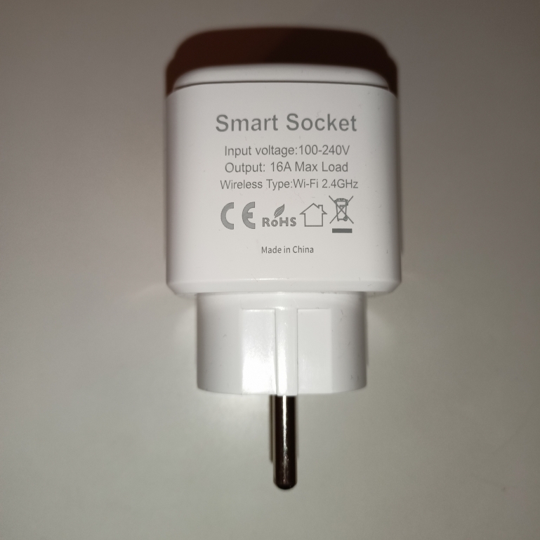
Recently, I’ve bought a really cheap smart socket with power monitoring for less than 6€ / 27PLN. The specification says that they can handle up to 16A of current, so it can be used to monitor energy consumption of all the devices I own (except induction stove, but well…). The manufacturer says that the socket can work with Tuya Smart app, Google Assistant and Alexa out-of-the-box, but this is not what I’m interested in. Let’s flash Tasmota there!
There are 2 main ways to install Tasmota to the ESP-based device:
- the easiest is to use tyua-convert that mimics firmware update server and tells the device to load the custom firmware over-the-air (so-called OTA update),
- if the first method fails, you can connect to ESP’s serial console and flash the firmware over wires.
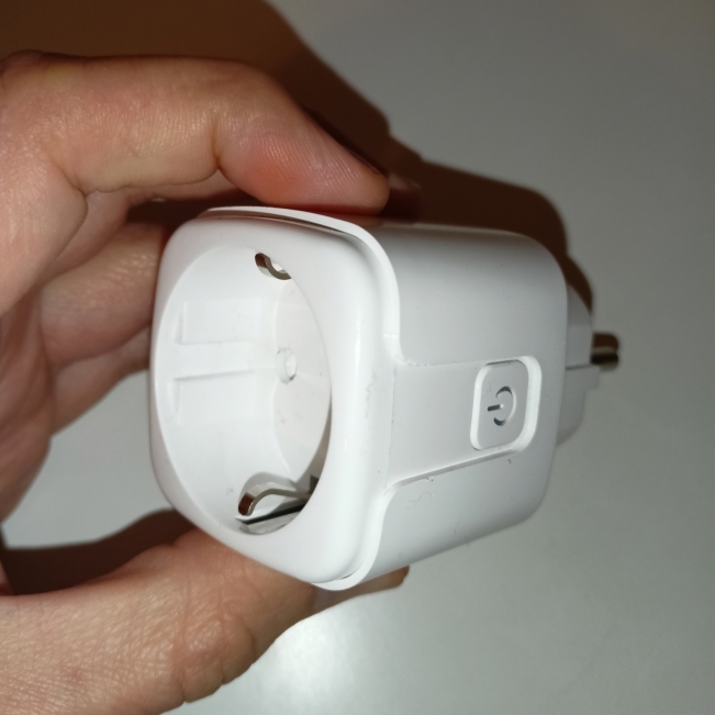
In the case of my cheap smart socket, the first method fails (as the new chips are protected from custom OTA flashing), so we will need a bit of hacking to get into it. The first challenge is opening the case - it cannot be done with a screwdriver, as the case is glued. Fortunately, applying a little force helps and we’re inside really quickly.
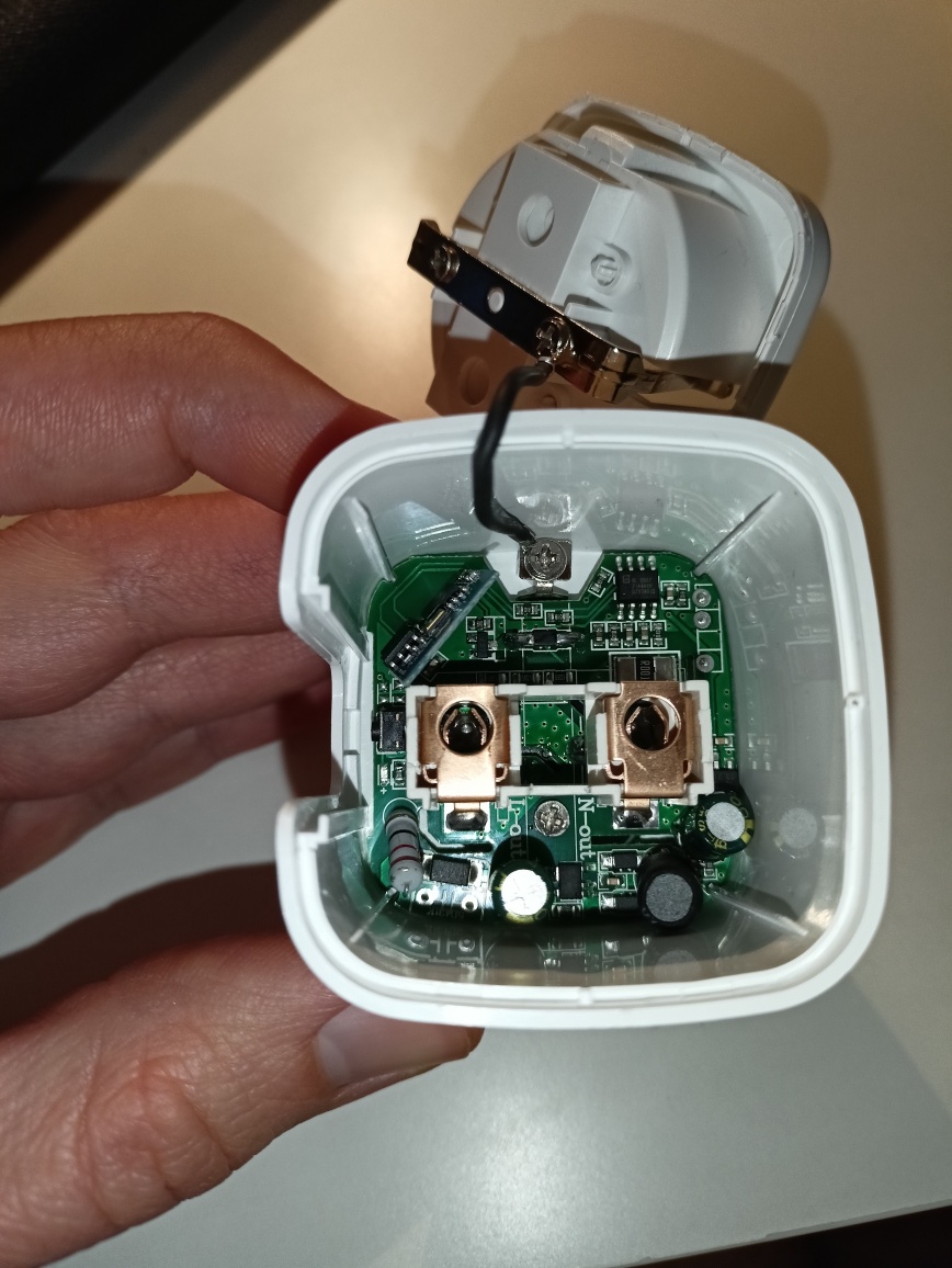
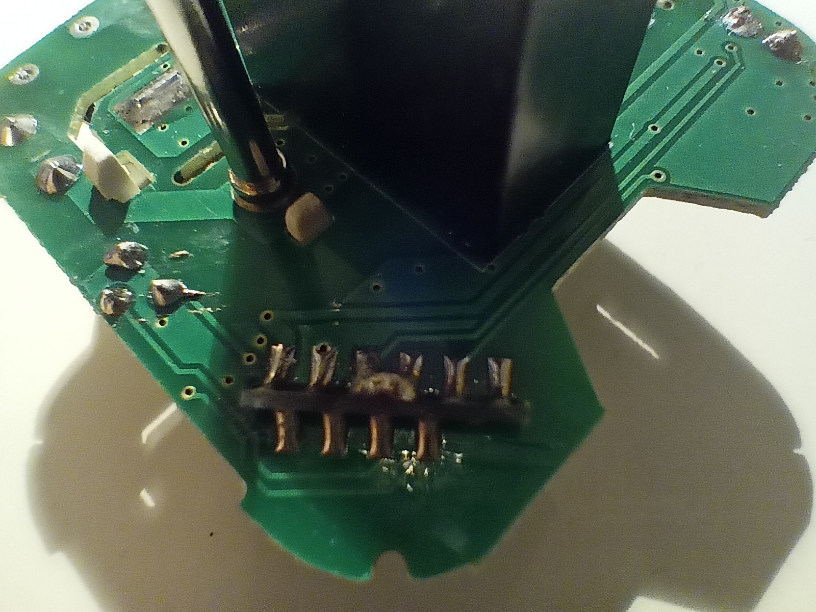
Two more screws and we have a mainboard off the case. The first thing you will notice on the bottom side is that 2 pads on ESP board are shorted. I’ve backtracked these to be TX and RX pings (GPIO 1 and 3) so we need to separate these to perform flashing:
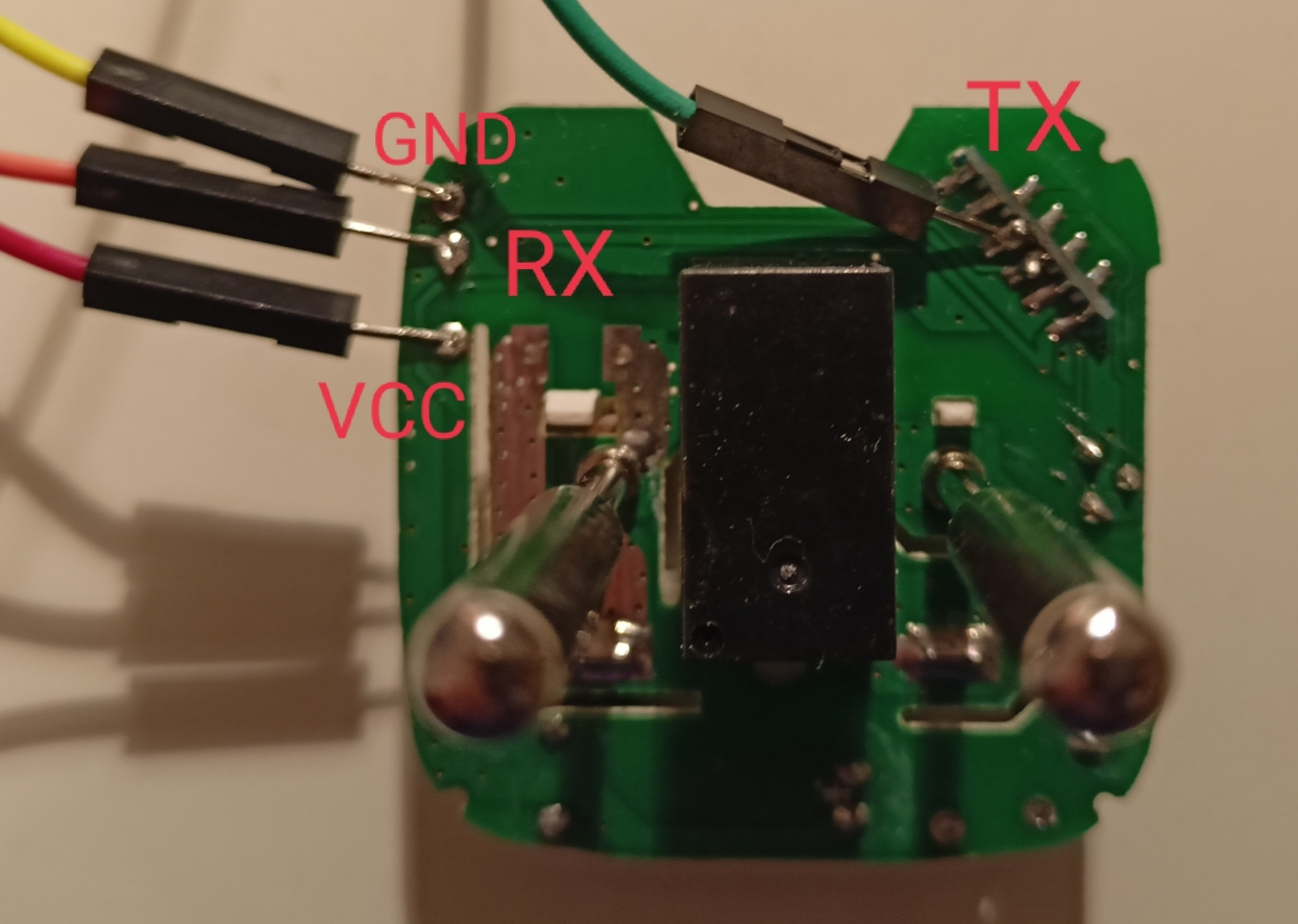
After separating, connect the board to the FTDI connector using the following setup:
- ESP VCC (test pad) to FTDI VCC,
- ESP GND (test pad) to FTDI GND,
- ESP RX (test pad) to FTDI TX,
- ESP TX (on the board, right side of the picture) to FTDI RX.
I suggest soldering all of these temporarily, as you will need to flip the mainboard upside down in a few moments.
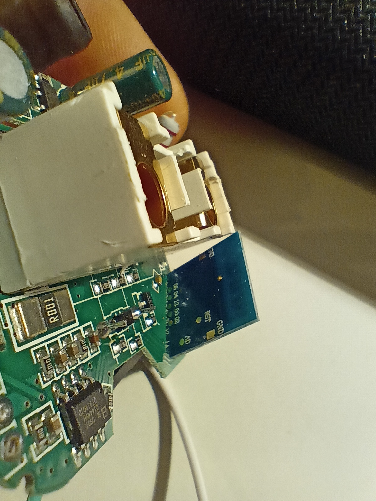
To perform flashing, you need to put the ESP into flashing mode by linking GPIO 02 with GND while powering up. Both 02 and GDN are available on the backside of the ESP board, so it’s quite easy to short them without soldering.
After ESP is powered on, the flash_id command of esptool should give you the following result:
$ esptool.py flash_id
esptool.py v3.2
Found 1 serial ports
Serial port /dev/ttyUSB0
Connecting...
Detecting chip type... Unsupported detection protocol, switching and trying again...
Connecting...
Detecting chip type... ESP8266
Chip is ESP8266EX
Features: WiFi
Crystal is 26MHz
MAC: 94:b9:7e:10:01:1e
Stub is already running. No upload is necessary.
Manufacturer: 5e
Device: 6014
Detected flash size: 1MB
Hard resetting via RTS pin...
Flash size 1MB is enough to flash Tasmota Lite, so this is the one to download from the release server. Before flashing, it’s a good practice to backup the existing firmware, just in case:
$ esptool.py read_flash 0x00000 0x100000 image1M.bin
esptool.py v3.2
Found 1 serial ports
Serial port /dev/ttyUSB0
Connecting...
Detecting chip type... Unsupported detection protocol, switching and trying again...
Connecting...
Detecting chip type... ESP8266
Chip is ESP8266EX
Features: WiFi
Crystal is 26MHz
MAC: 94:b9:7e:10:01:1e
Stub is already running. No upload is necessary.
1048576 (100 %)
1048576 (100 %)
Read 1048576 bytes at 0x0 in 98.2 seconds (85.5 kbit/s)...
Hard resetting via RTS pin...
Then it’s finally the time to install tasmota lite!
$ esptool.py erase_flash
esptool.py v3.2
Found 1 serial ports
Serial port /dev/ttyUSB0
Connecting...
Detecting chip type... Unsupported detection protocol, switching and trying again...
Connecting...
Detecting chip type... ESP8266
Chip is ESP8266EX
Features: WiFi
Crystal is 26MHz
MAC: 94:b9:7e:10:01:1e
Stub is already running. No upload is necessary.
Erasing flash (this may take a while)...
Chip erase completed successfully in 4.7s
Hard resetting via RTS pin...
$ esptool.py write_flash -fs 1MB -fm dout 0x0 tasmota-lite.bin
esptool.py v3.2
Found 1 serial ports
Serial port /dev/ttyUSB0
Connecting...
Detecting chip type... Unsupported detection protocol, switching and trying again...
Connecting...
Detecting chip type... ESP8266
Chip is ESP8266EX
Features: WiFi
Crystal is 26MHz
MAC: 94:b9:7e:10:01:1e
Stub is already running. No upload is necessary.
Configuring flash size...
Flash will be erased from 0x00000000 to 0x0007dfff...
Compressed 513392 bytes to 366235...
Wrote 513392 bytes (366235 compressed) at 0x00000000 in 32.3 seconds (effective 127.3 kbit/s)...
Hash of data verified.

Leaving...
Hard resetting via RTS pin...
After this step, ESP board should be restarted so Tasmota can be loaded. Shortly after, you should see the new 2.4 GHz wifi network with tasmota prefix:
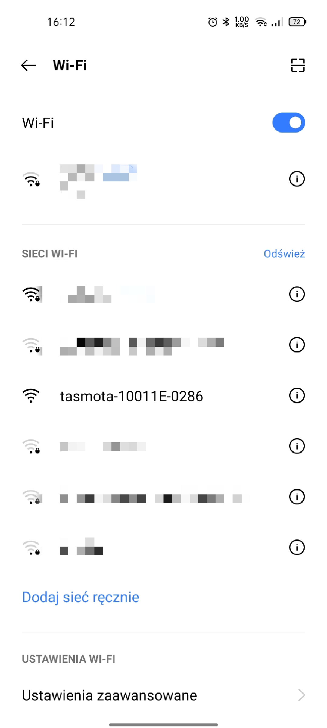
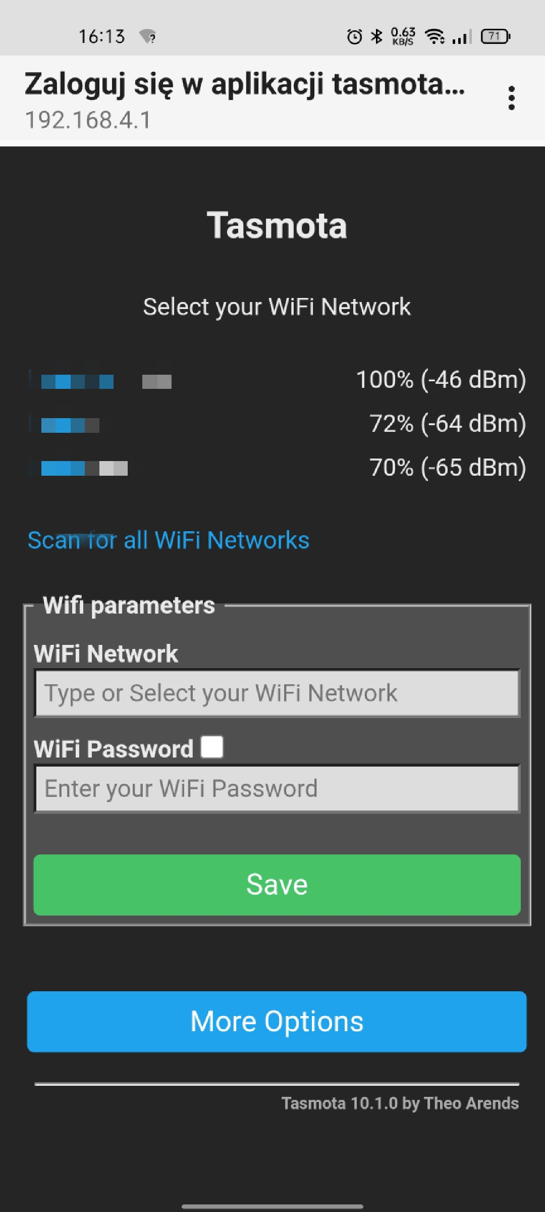
Connect to this network, go to http://192.168.4.1 and configure your router credentials:
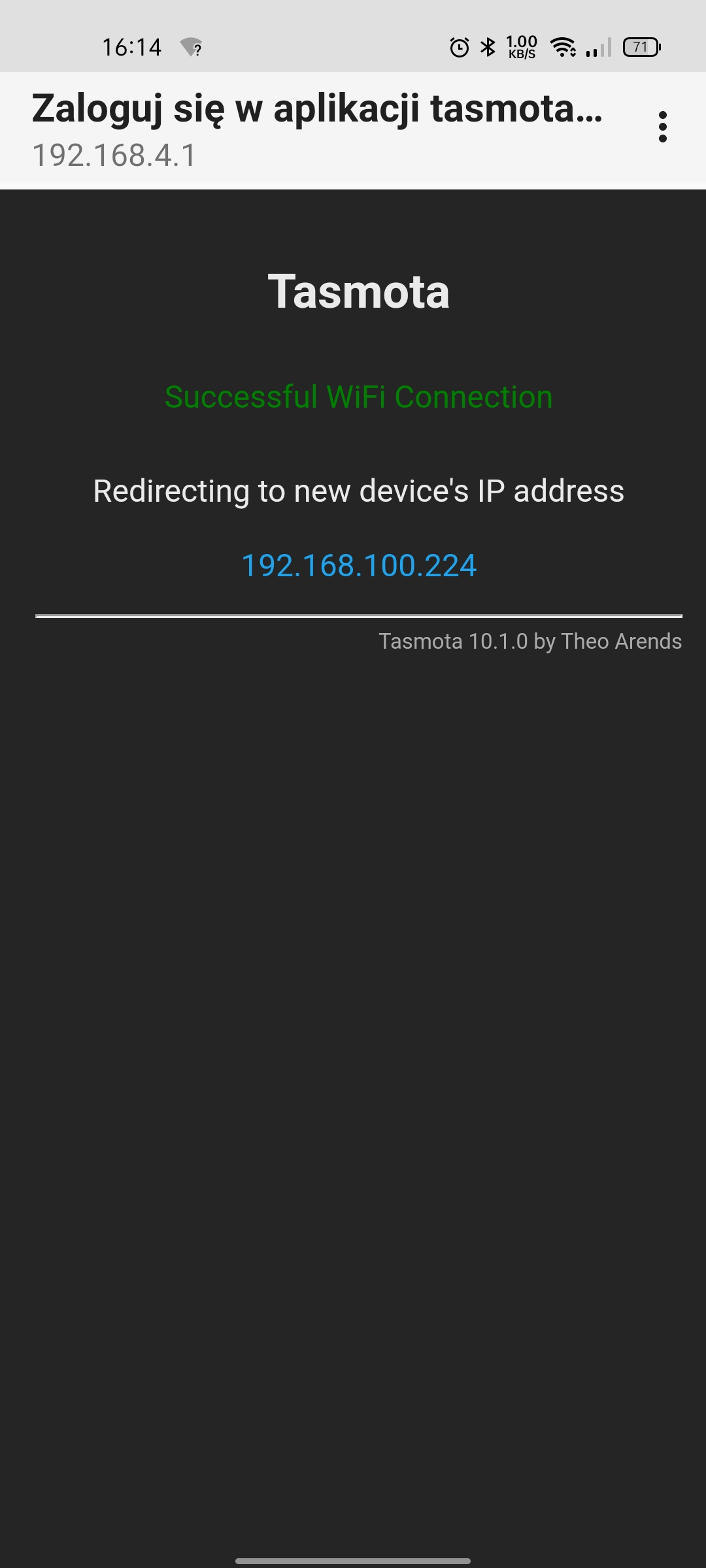
If everything is OK, the device IP will be displayed:
And you can access it from any device connected to the main Wifi network:
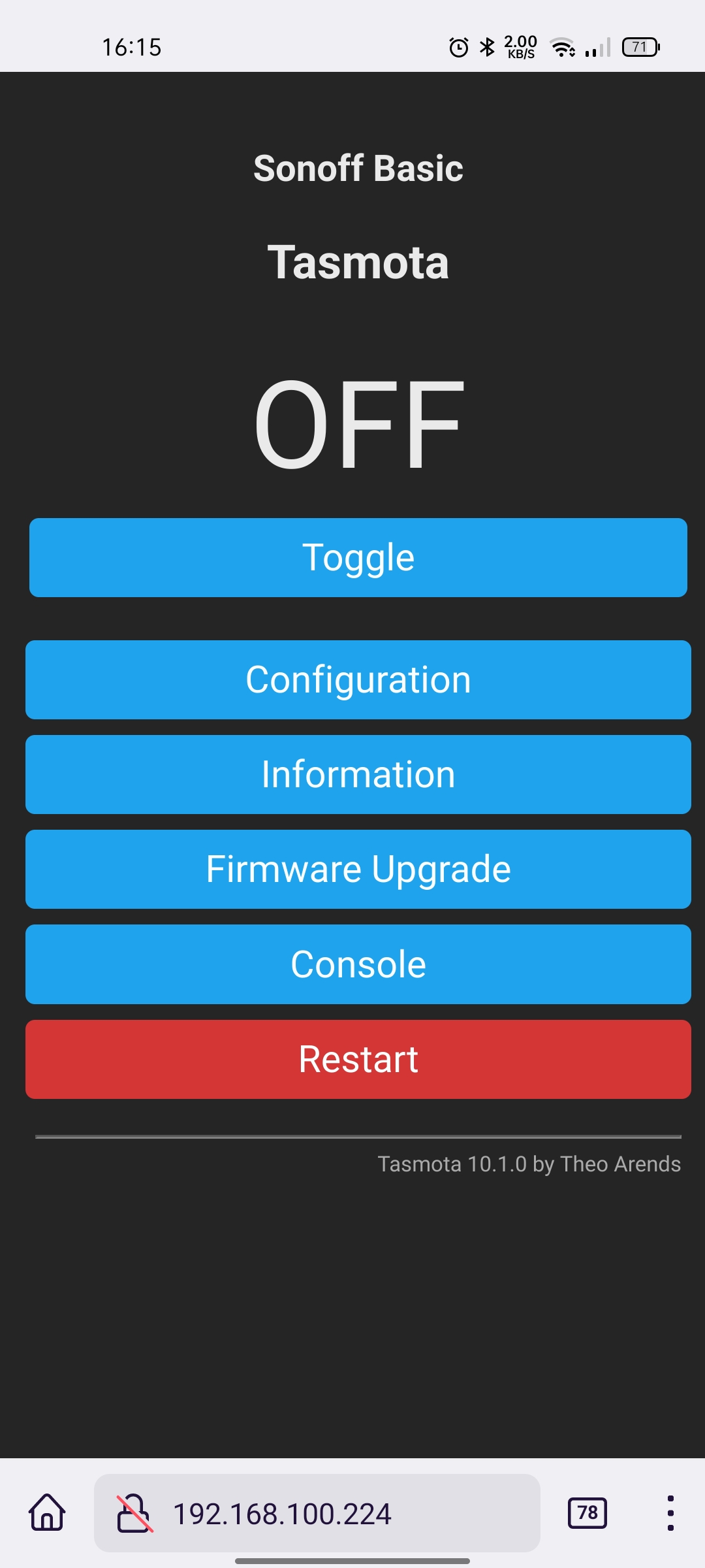
By default, the firmware has no configuration, but we can handle it later. Desolder all the cables and put the device back in the case. Do not forget to put super glue on the top of the case, otherwise, you may damage the smart socket while unplugging things.
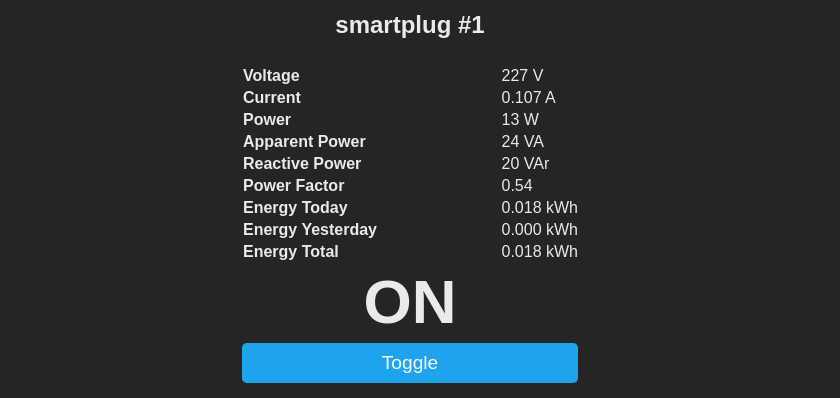
When device is up, go to Tasmota UI -> Configuration -> Configure Other and enter the following Template:
{"NAME":"Smart Socket","GPIO":[0,32,0,0,2720,2656,0,0,2624,320,224,0,0,0],"FLAG":0,"BASE":18}
Then, after a short auto-restart, the smart socket should be fully functional with led (indicating power status), button, relay and power monitoring. You may need to calibrate the sensor to fully enjoy the smart socket capabilities.